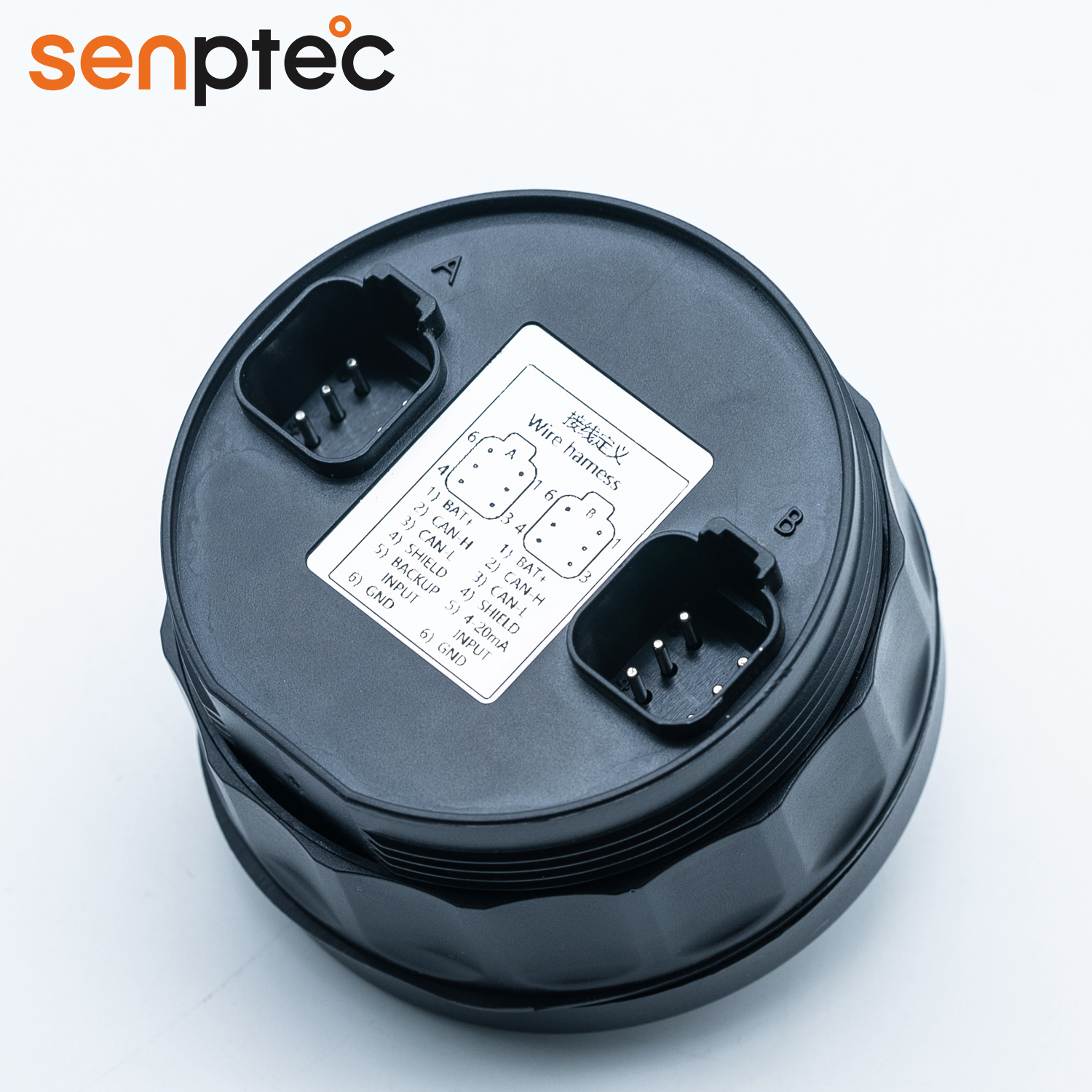
Dimensions, Wiring and Pins
1、Wiring Instructions:
pin 1 is the power cord, which needs to be connected to ACC or ON switch;
pin 2,3 are CAN communication line, which is connected to engine ECU after twisted-pair; When the engine is not electronically controlled, the three wires are not connected;
pin 4 is the shield line of CAN line;
pin 5 is analog/frequency input;
Plug end model:Deutsch DT06-6S;
pin 6 is ground wire, which needs to be connected with wire.
2、Signal Source:
The instrument works preferentially from CAN signal, if there is no CAN signal, it works according to sensor signal, but the customer needs to provide sensor parameters.